ESPAÑOL
Hola colegas, hoy quiero mostrar mi experiencia durante la reparación del motor del compartimento de secado de una lavadora semiautomática, también les comentaré el procedimiento para medir y dictaminar el estado técnico de dicho motor, para que sirva de ayuda a todas esas personas que intenten resolver en casa este tipo de problemas.
¿Te ha sucedido que mientras utilizas la lavadora deja de funcionar el compartimento de secado?
Bueno, este problema es común y podría estar dado precisamente producto a un motor defectuoso. Aunque no es el único causante de este problema, ya que existen otras causas por las que podría dejar de funcionar el centrifugado y que deberían ser analizadas antes de pasar a medir el motor, no haré mención de ellas, ya que el objetivo de la publicación es mostrar como medir estos motores una vez que se han descartado el resto de las probables causas del fallo.
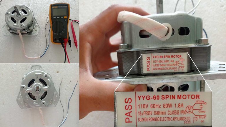
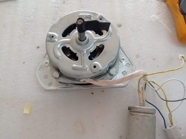
Motor de giro rápido, para lavadora, modelo YYG-60.
Como se ve en la imagen anterior, este es un motor monofásico de giro rápido, debe emplear un condensador de arranque de 18 microfaradio(uF)/ 250 volt; modelo:YYG-60. Es de 60 watts de potencia, y se alimenta con 110 volts a una frecuencia de 60 Hertz (Hz).
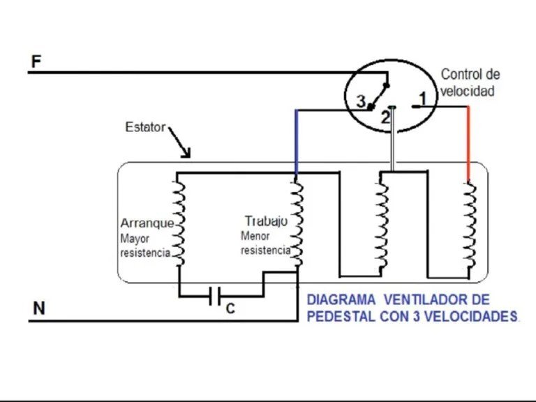
Estos motores internamente presentan dos bobinados, uno de Trabajo (R) y otro de Arranque (S), uno de los extremos de cada bobina se unen en un punto, entre dicho punto y uno de los tres cables que salen del interior del motor se intercala un fusible térmico para la protección, en este caso el cable se denomina Común(C) y es el cable Azul, en el cual se conecta el neutro de la red eléctrica. El otro cable (en este caso es el cable Gris) es el de Arranque y corresponde al otro extremo del bobinado de arranque. El extremo del bobinado de Trabajo, además de estar conectado al punto común, se conecta por el extremo opuesto al cable blanco. El condensador debe de ir conectado entre el terminal de la bobina de Trabajo y el terminal de la bobina de arranque, específicamente para este motor debe conectarse entre el cable Gris y el cable Blanco como bien se representa en la información del motor, mostrada en la imagen anterior. En la siguiente imagen les muestro un esquema de la construcción interna del motor.
Esquema eléctrico del motor, se aprecian las dos bobinas unidas en un punto común, el fusible térmico, las conexiones de los tres cables que salen de la carcasa del motor y los puntos donde se conecta el capacitor. Los colores de la representación están en correspondencia con los colores de los cables del motor, excepto el cable rojo, que corresponde con el cable blanco del motor físico
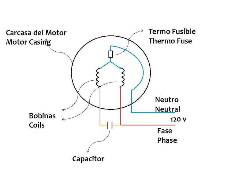
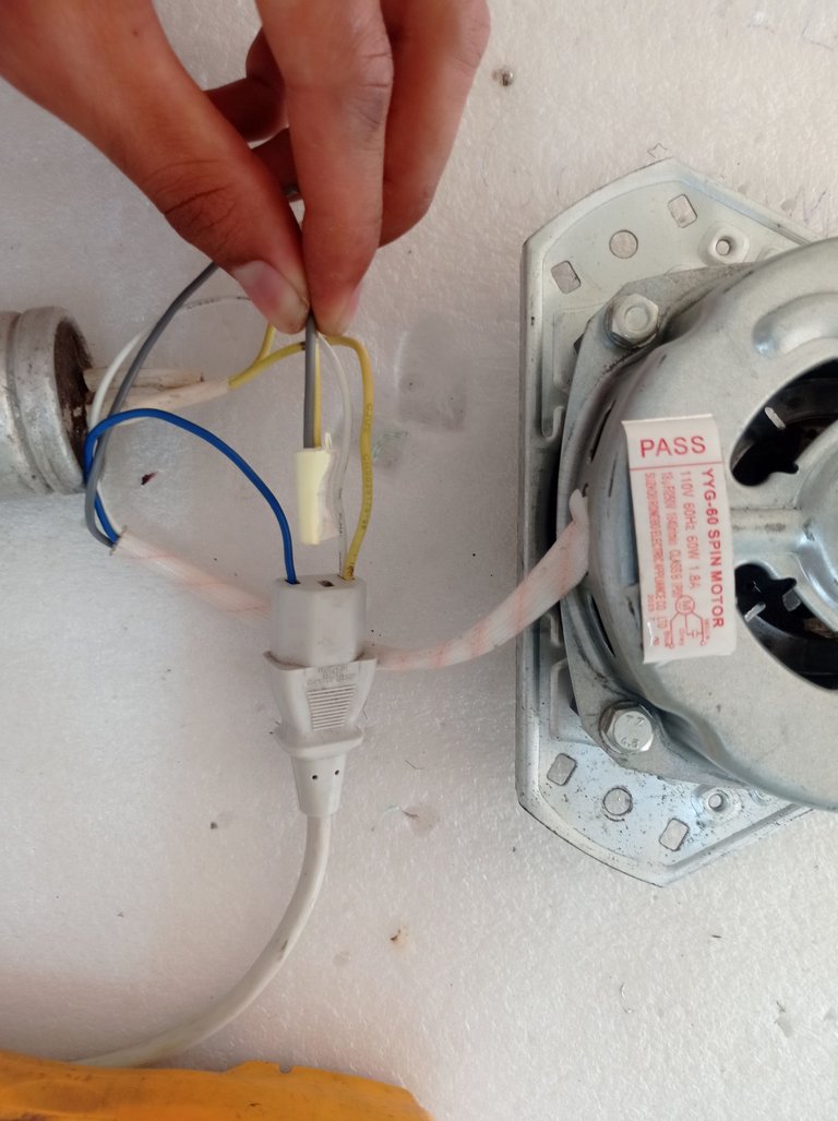
En la siguiente imagen muestro en la práctica los puntos donde se deben conectar el capacitor y la alimentación eléctrica.
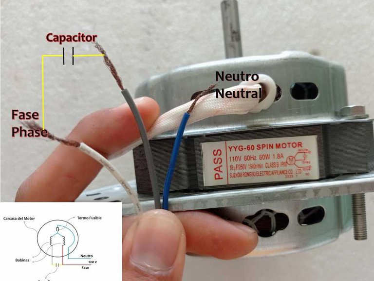
Como se puede apreciar, uno de los extremos del capacitor debe conectarse al cable Blanco y el otro extremo al cable Gris, al mismo tiempo se conecta el neutro de la alimentación al cable Azul y la Fase o línea viva al cable Blanco.
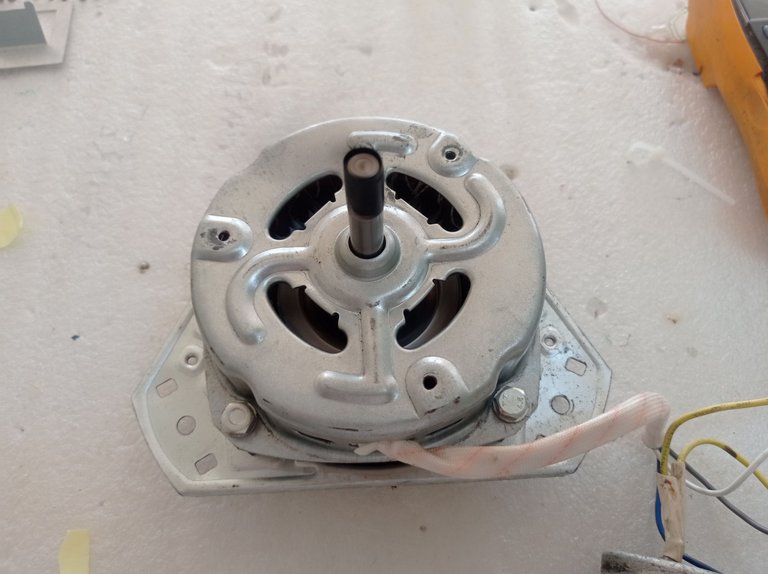
Una vez conocida la construcción general del motor, veremos su desarme completo, sus partes y el procedimiento para realizar las mediciones pertinentes que permitan determinar si se encuentra en buen estado.
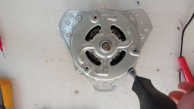
Para desarmar este tipo de motor se deben extraer los cuatro tornillos de cabeza hexagonal con ayuda de una llave de cubos. Luego se separa una de las tapas de la carcasa tirando de ella hacia arriba con mucho cuidado de no provocar daño al enrollado interno, el proceso se muestra en la siguiente imagen.
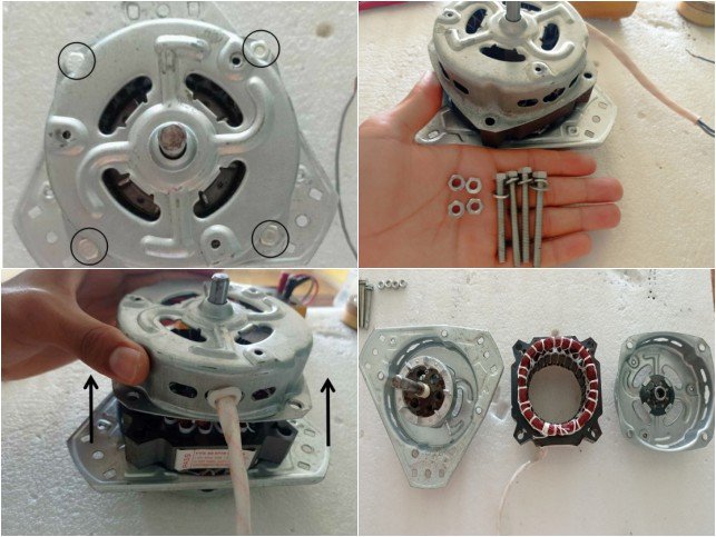
Proceso de desarme
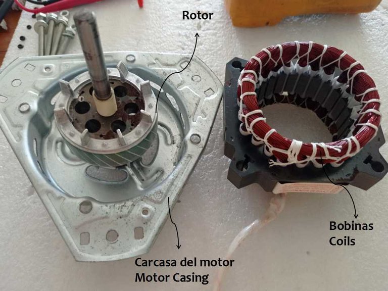
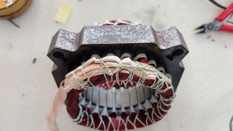
Rotor, Carcasa del motor y Estator con su bobinado
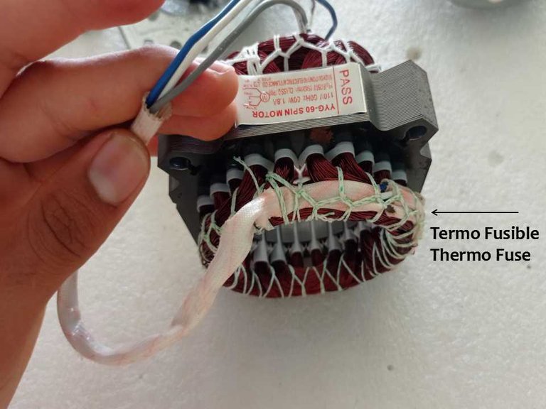
En la zona señalada, envuelto por el aislante, se localiza el fusible térmico de protección.
Para determinar el estado técnico del motor se debe medir el bobinado empleando un Multímetro y a continuación describiré los pasos.
- Primeramente se debe preparar el multímetro para medir resistencia, para ello se coloca el selector en la posición correspondiente al símbolo Ω y estará listo para medir la resistencia del alambre de la bobina.

Multímetro listo para medir resistencia
- El siguiente paso consiste en realizar tres posibles mediciones en la que se obtendrán tres valores de baja resistencia si las bobinas se encuentran en buen estado, de estos tres valores existirá uno más pequeño, otro intermedio y otro mayor, de las tres mediciones el de mayor valor corresponde a la suma del valor pequeño con el intermedio y el cable que quede libre al obtenerse el mayor valor corresponderá al cable común. Si se obtienen valores de alta resistencia o resistencia infinita, las bobinas o una de ellas se encuentra en mal estado, este último resultado pudiera deberse también a un fusible térmico en mal estado.
Se debe realizar una cuarta medición que consiste en chequear que exista el aislamiento correcto entre los cables del motor y su cuerpo metálico. Si no existen problemas de aislamiento, la resistencia tiene que ser de un valor infinito o de elevada resistencia. Una baja resistencia entre los cables y el cuerpo metálico del motor es sinónimo de que existen espiras del bobinado con problemas de aislamiento y se encuentran en contacto con el cuerpo del motor, lo que provocaría un mal funcionamiento del mismo.
Para medir, se toma uno de los tres cables que salen del motor y se conecta a una de las puntas del multímetro, la otra punta del multímetro se conecta a cualquiera de los otros dos cables restantes y se toma lectura de la resistencia entre los cables seleccionados.
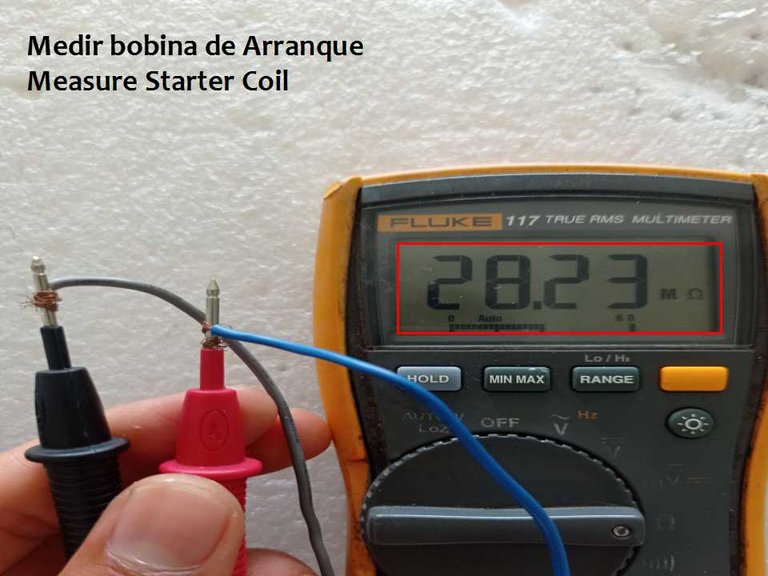
Como se puede observar, para la medición seleccioné el cable azul y el cable gris, dando como resultado un valor de 28,23 megaohm (MΩ) lo que corresponde con una alta resistencia que significa que el bobinado está en mal estado o que el fusible térmico está averiado
- Para la siguiente medición se debe mantener fijo uno de los dos cables y combinarlo con el otro cable restante para tomar la lectura de resistencia.
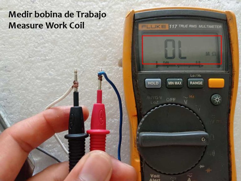
En este caso mantuve el cable azul y lo combiné con el cable blanco, dando como resultado un valor de resistencia infinita, ya que el multímetro marcó un resultado de OL MΩ el cual corresponde a valores infinitos
- La tercera medición se realiza entre los dos cables que no se han combinado entre sí
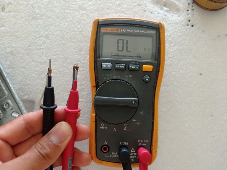
Los cables que quedan por combinar entre sí son el blanco y el gris y como se puede observar el resultado arrojó una resistencia infinita, corroborando la existencia de una avería en el bobinado del motor o un mal estado del fusible térmico.
.
De los resultados anteriores se concluye que el motor presenta problemas en las conexiones internas. A modo de resumen, el procedimiento para realizar las mediciones en estos motores de tres cables, es el siguiente:
- Se realizan tres mediciones para determinar la resistencia entre las tres combinaciones de cables, ejemplo: Azul-Gris; Azul-Blanco y Blanco-Gris.
- Si las bobinas están en buen estado se obtendrán tres valores de resistencia, uno pequeño, uno intermedio y uno mayor, este último será la suma del valor pequeño con el intermedio. Destacar que el valor pequeño corresponde a la resistencia de la bobina de trabajo y el valor intermedio a la resistencia de la bobina de arranque.
- Al obtenerse el mayor valor de resistencia se deben marcar los cables entre los cuales se obtuvo y el cable que queda libre corresponde al Común(C).
- Si se obtienen valores altos de resistencia o infinitos, existen averías en las conexiones internas del motor.
- Se debe comprobar el aislamiento total entre los cables que salen del motor y el cuerpo del mismo.
Como el bobinado del motor se observa en buenas condiciones físicas, trataré de reparar la avería y luego repetir las mediciones para que quede demostrado a modo de ejemplo el procedimiento descrito anteriormente.
El bobinado se encontraba en buenas condiciones físicas, así que me queda sospechar del fusible térmico o que el alambre esté quebrado en algún tramo. Localizaré primeramente el fusible térmico, el mismo se encuentra normalmente debajo del aislante, por lo que es necesario abrir el aislante con el cutter.
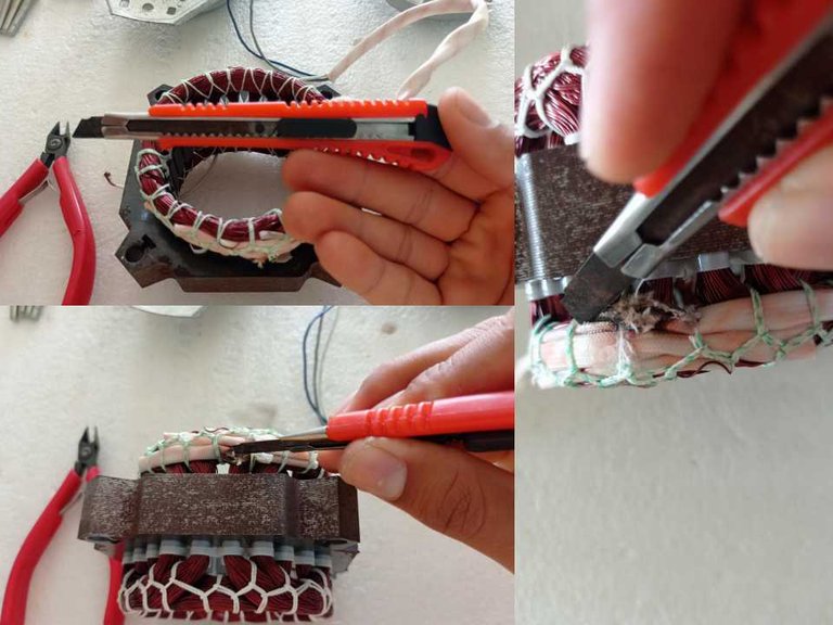
Con ayuda de un cutter, trato de localizar el fusible térmico para medirlo.
Sin embargo, buscando me sorprendió ver que en el lugar donde debería estar alojado el fusible solo existía una conexión directa entre el cable azul (C) y los extremos de las bobinas de trabajo y arranque, además esta conexión estaba en mal estado y era la avería que provocaba un desperfecto en el motor. Imagino que este motor fue reparado en otro momento y no se le colocó el fusible térmico.
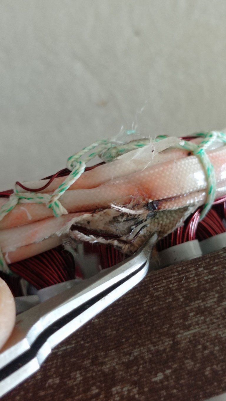
La conexión carece de fusible y además se encuentra partida por calentamiento
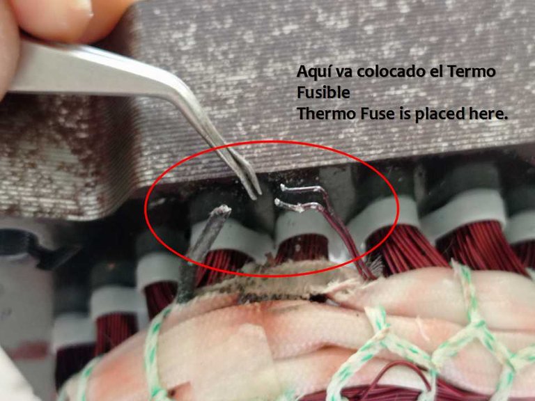
Aquí debe ir colocado el Fusible térmico
Lo siguiente será reparar esta avería uniendo nuevamente los extremos de las bobinas con el cable Azul(C), no colocaré fusible térmico, ya que no cuento con ninguno de repuesto; sin embargo, de esta forma podré hacer nuevamente las mediciones y mostrar los resultados cuando el motor está en buenas condiciones.
- Con la ayuda del cutter se deben raspar las puntas de las bobinas con el objetivo de quitarle el barniz que actúa como aislante.
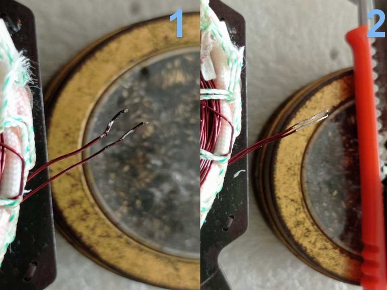
Eliminar el barniz de las puntas del alambre
Luego fue necesario cortar parte del hilo que asegura el grupo de cables que salen del motor, con el objetivo de alargar el cable azul para cortar el tramo en mal estado y conectarlo nuevamente con las puntas de los alambres de los bobinados que fueron raspadas anteriormente. Este proceso se observa en las siguientes imágenes y para la unión utilicé un soldador cautín y estaño.
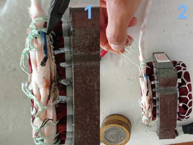
Cortar hilo
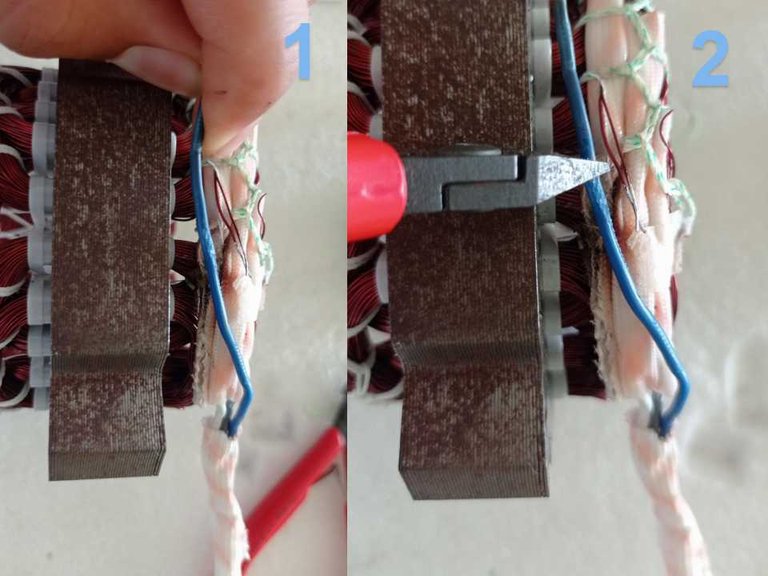
Alargar el cable azul para cortar la punta en mal estado producto al calentamiento
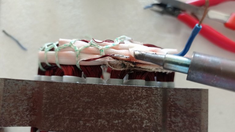
Soldando las puntas con ayuda del cautín
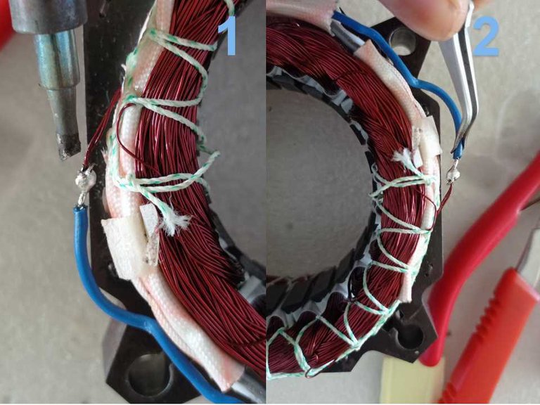
Luego se debe aislar todo como estaba antes para evitar cortos entre los cables.
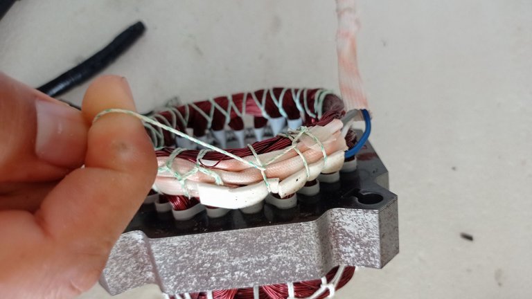
Aproveche el mismo hilo para ajustar los cables
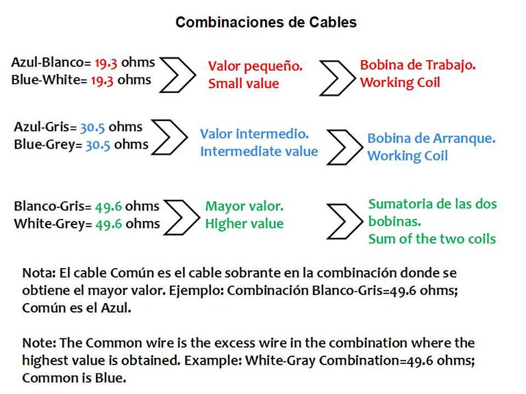
Luego de haber corregido el problema haremos nuevamente las mediciones. Escogeré dos cables, en este caso serán Azul-Blanco, luego Azul-Gris y por último Blanco-Gris, en todos los casos medí la resistencia y anoté el valor en un papel con las combinaciones de cables correspondientes, identificando el valor más pequeño, el intermedio y el mayor. El valor más pequeño corresponde a la bobina de trabajo, el intermedio a la de arranque, y el mayor valor es la sumatoria de ambas bobinas.
El cable común es el cable sobrante en la combinación donde se obtiene el mayor valor de resistencia, en este caso es el Azul, pues sobra en la combinación Blanco-Gris que presenta una resistencia de 49.6 ohms, como se observa en las siguientes imágenes.
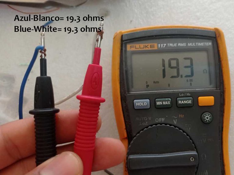
Combinación Azul-Blanco con una resistencia de 19.3 ohms.
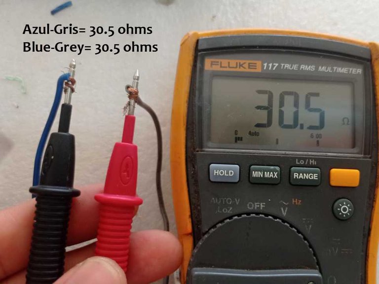
Combinación Azul-Gris con una resistencia de 30.5 Ohms
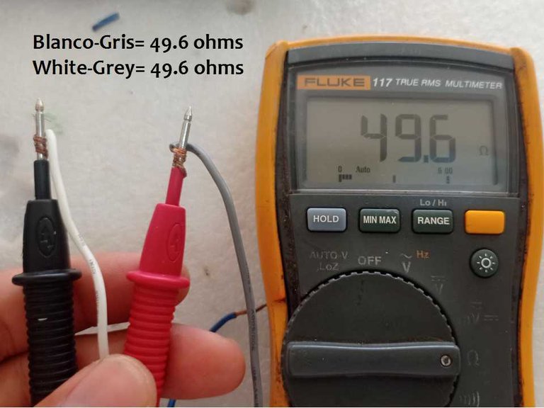
Combinación Blanco-Gris con una resistencia de 49.6 ohms, es el mayor valor obtenido.
Anotaciones de los valores medidos para identificar los terminales del motor
De esta forma se pueden identificar los cables de este tipo de motores aun sin tener la información de la chapa (en este caso el motor tenía la chapa) y siguiendo este procedimiento se pueden medir los motores monofásicos de tres cables como el de la secadora de la lavadora. El motor de la tina de lavado es similar con la diferencia que el valor de la resistencia de las dos bobinas debe ser igual, debido a que en un intervalo de tiempo debe trabajar en un sentido y en otro intervalo de tiempo trabaja en el sentido contrario; sin embargo, el procedimiento para medir es el mismo.
Conexionado y pruebas finales.
Después de reparar y medir, lo siguiente fue conectar un capacitor y probar el funcionamiento del motor en la red eléctrica de 120 volts.
Armar el motor nuevamente
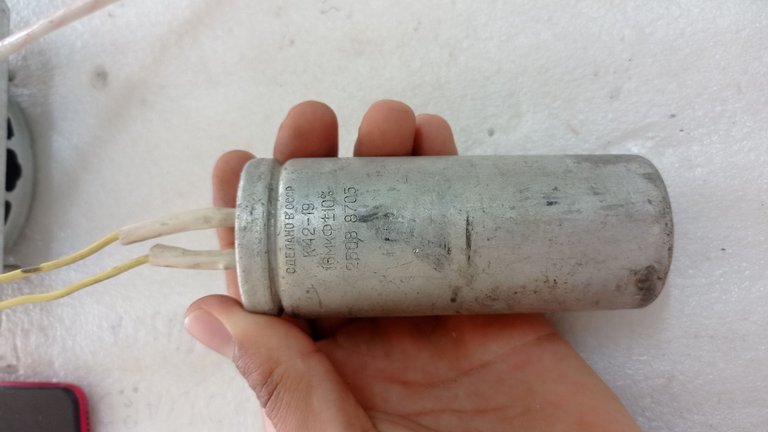
Capacitor de 16 microfaradio(uF) / 250 volts, para probar el funcionamiento (el ideal es de 18 uF)
Conectar un extremo del capacitor al cable Gris, el otro extremo se conecta al cable Blanco, la alimentación de 120 Volts va entre el cable Azul y la unión del Blanco con uno de los extremos del capacitor
Motor en funcionamiento
Espero que esta información sirva de ayuda para otras personas, sin más me despido deseándoles un excelente día.
Un saludo y hasta el próximo post 😉
Las imágenes fueron tomadas con un celular Xiaomi Redmi Note 9.
Imágenes editadas en la aplicación "WPS Presentation"
Portada creada en Canva
Puedes verme en Facebook
ENGLISH
Hello colleagues, today I want to show you my experience during the repair of the motor of the drying compartment of a semi-automatic washing machine, I will also tell you the procedure to measure and determine the technical condition of the motor, to help all those people who try to solve this kind of problems at home.
Has it ever happened to you that while you are using the washing machine, the drying compartment stops working?
Well, this problem is common and could be caused by a defective motor. Although it is not the only cause of this problem, since there are other causes that could stop spinning and that should be analyzed before measuring the motor, I will not mention them, since the purpose of the publication is to show how to measure these motors once the rest of the probable causes of the failure have been discarded.
Quick turn motor, for washing machine, model YYG-60.
As seen in the picture above, this is a single-phase fast-turn motor, it should employ an 18 microfarad (uF)/ 250 volt starting capacitor; model:YYG-60. It is 60 watts of power, and is powered by 110 volts at a frequency of 60 Hertz (Hz).
Internal to these motors there are two windings, one working winding (R) and one starting winding (S), one of the ends of each winding are joined at a point, between this point and one of the three wires coming out from inside the motor a thermal fuse is inserted for protection, in this case the wire is called Common (C) and it is the Blue wire, in which the neutral of the electrical network is connected. The other wire (in this case it is the Gray wire) is the Start wire and corresponds to the other end of the start winding. The end of the working winding, besides being connected to the common point, is connected at the opposite end to the white wire. The capacitor must be connected between the terminal of the work coil and the terminal of the starting coil, specifically for this motor it must be connected between the gray wire and the white wire, as it is well represented in the information of the motor, shown in the previous image. In the following image, I show a schematic of the internal construction of the motor.
Electrical diagram of the motor, showing the two coils joined at a common point, the thermal fuse, the connections of the three wires coming out of the motor casing and the points where the capacitor is connected. The colors of the representation correspond to the colors of the motor wires, except for the red wire, which corresponds to the white wire of the physical motor.
In the following image I show the points where the capacitor and the power supply must be connected.
As can be seen, one end of the capacitor must be connected to the White wire and the other end to the Grey wire, at the same time the neutral of the power supply is connected to the Blue wire and the Phase or live line to the White wire.
Once the general construction of the engine is known, we will see its complete disassembly, its parts and the procedure to perform the pertinent measurements to determine if it is in good condition.
To disassemble this type of motor, the four hex head screws must be removed using a socket wrench. Then separate one of the covers from the casing by pulling it upwards, being very careful not to damage the internal winding, the process is shown in the following image.
Dismantling process
Rotor, Motor Housing and Stator with winding
The thermal protection fuse is located in the indicated area, enclosed by the insulation.
To determine the technical condition of the motor, the winding must be measured using a multimeter and I will describe the steps below.
- First, the multimeter must be prepared to measure resistance by placing the selector switch in the position corresponding to the Ω symbol and it will be ready to measure the resistance of the coil wire.
Multimeter ready to measure resistance
The next step is to perform three possible measurements in which three values of low resistance will be obtained if the coils are in good condition, of these three values there will be a smaller one, an intermediate one and a larger one, of the three measurements the largest value corresponds to the sum of the small value with the intermediate one and the wire that is free when the largest value is obtained corresponds to the common wire. If high resistance or infinite resistance values are obtained, the coils or one of them is in bad condition, this last result could also be due to a thermal fuse in bad condition.
A fourth measurement should be made to check for proper insulation between the motor leads and the motor's metal body. If there are no insulation problems, the resistance must be of infinite value or high resistance. A low resistance between the wires and the metal body of the motor means that there are winding turns with insulation problems and they are in contact with the motor body, which would cause the motor to malfunction.
To measure, one of the three wires coming out of the motor is taken and connected to one end of the multimeter, the other end of the multimeter is connected to either of the other two remaining wires and a resistance reading is taken between the selected wires.
As can be seen, for the measurement I selected the blue wire and the gray wire, resulting in a value of 28.23 megaohm (MΩ) which corresponds to a high resistance which means that the winding is in bad condition or that the thermal fuse is faulty.
- For the next measurement, hold one of the two wires steady and combine it with the other remaining wire to take the resistance reading.
In this case I kept the blue wire and combined it with the white wire, resulting in an infinite resistance value, since the multimeter marked a result of OL MΩ which corresponds to infinite values.
- The third measurement is made between the two cables that have not been combined with each other.
The wires that remain to be combined are white and gray and, as can be seen, the result showed an infinite resistance, corroborating the existence of a fault in the motor winding or a bad condition of the thermal fuse.
.
From the above results it can be concluded that the motor presents problems in the internal connections. By way of summary, the procedure to perform the measurements on these three-wire motors is as follows:
- Three measurements are made to determine the resistance between the three wire combinations, e.g. Blue-Grey; Blue-White and White-Grey.
- If the coils are in good condition, three resistance values will be obtained, a small one, an intermediate one and a larger one, the latter will be the sum of the small value with the intermediate one. Note that the small value corresponds to the resistance of the working coil and the intermediate value to the resistance of the starting coil.
- When the highest resistance value is obtained, the wires between which it was obtained must be marked and the free wire corresponds to Common(C).
- If high or infinite resistance values are obtained, there are faults in the internal connections of the motor.
- The total insulation between the cables coming out of the motor and the motor body must be checked.
As the motor winding appears to be in good physical condition, I will try to repair the fault and then repeat the measurements to demonstrate the procedure described above as an example.
The winding was in good physical condition, so I suspect the thermal fuse or that the wire is broken in some section. I will first locate the thermal fuse, which is usually located under the insulator, so it is necessary to open the insulator with the cutter.
With the help of a cutter, I try to locate the thermal fuse to measure it.
However, I was surprised to see that in the place where the fuse should be located there was only a direct connection between the blue wire (C) and the ends of the working and starting coils, and this connection was in bad condition, and it was the fault that caused a malfunction in the motor. I imagine that this motor was repaired at another time and the thermal fuse was not placed.
The connection lacks a fuse and is also split due to heating.
The thermal fuse must be placed here.
The next step will be to repair this fault by reattaching the ends of the coils with the Blue wire (C), I will not place a thermal fuse, since I do not have any spare; however, this way I will be able to make the measurements again and show the results when the motor is in good condition.
- With the help of the cutter, the ends of the coils should be scraped to remove the varnish that acts as an insulator.
Removing varnish from wire ends.
Then it was necessary to cut part of the wire that secures the group of wires coming out of the motor, with the objective of lengthening the blue wire to cut the section in bad condition and connect it again with the tips of the wires of the windings that were previously scraped. This process is observed in the following images, and for the union I used a soldering iron and tin.
Cutting thread
Lengthen the blue wire to cut the tip in bad condition due to overheating.
Soldering the tips using a soldering iron
Then everything must be insulated as it was before to avoid shorts between the wires.
Use the same wire to adjust the cables.
After having corrected the problem, we will do the measurements again. I will choose two wires, in this case they will be Blue-White, then Blue-Grey and finally White-Grey, in all cases I measured the resistance and wrote down the value on a piece of paper with the corresponding wire combinations, identifying the smallest, the intermediate and the largest value. The smallest value corresponds to the working coil, the intermediate to the starting coil, and the largest value is the sum of both coils.
The common wire is the leftover wire in the combination where the highest resistance value is obtained, in this case it is the Blue one, because it is leftover in the White-Gray combination that presents a resistance of 49.6 ohms, as shown in the following images.
Blue-White combination with a resistance of 19.3 ohms.
Blue-Gray combination with a resistance of 30.5 Ohms
White-Gray combination with a resistance of 49.6 ohms is the highest value obtained..
Annotations of measured values to identify motor terminals.
In this way it is possible to identify the wires of this type of motors even without having the information of the plate (in this case the motor had the plate) and following this procedure it is possible to measure the single-phase motors of three wires like the one of the washer dryer. The washing tub motor is similar with the difference that the resistance value of the two coils must be equal, because in a time interval it must work in one direction and in another time interval it works in the opposite direction; however, the measuring procedure is the same.
Connection and final testing.
After repairing and measuring, the next step was to connect a capacitor and test the operation of the motor on the 120 volt mains.
Reassemble the motor
16 microfarad capacitor (uF) / 250 volts, to test the operation (the ideal is 18 uF).
Connect one end of the capacitor to the Gray wire, the other end is connected to the White wire, the 120 Volt power supply goes between the Blue wire and the junction of the White wire with one end of the capacitor.
Engine in operation
I hope this information will be of help to other people, without further ado I bid you farewell and wish you an excellent day.
Best regards and see you next post 😉La ima
The images were taken with a Xiaomi Redmi Note 9 cell phone.
Images edited in the "WPS Presentation" application.
Cover created in Canva
You can see me at Facebook