[PT]
Hello, Hive Community!
I'm studying for a master's degree in Electrical Engineering and I've decided to share my academic adventures whenever possible. Recently, I had the opportunity to enroll in Electronic Instrumentation. Although I love electronics, that doesn't guarantee that it will be easy or that I will do well!
In the first week of the course, the teacher prepared our first lab, which consists of measuring air flow. There are several methods for measuring flow, each with its own particularities. Some methods are more suitable for measuring flow at low speeds, while others are better for high speeds, among other variables. In short, measuring flow is a real challenge!
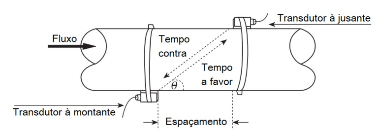
For our measurement, we will use ultrasonic transducers: a transmitter and a receiver. The experiment involves passing a stream of air through a tube, where an ultrasonic transmitter and receiver are fixed at an angle of 45º. But why 45º? These transducers emit sound waves (mechanical) above 20 kHz, which classifies them as ultrasonic. If they were positioned vertically, the mechanical waves could suffer a drag effect. To minimize this effect, the transducers are tilted, but still aligned in the same line of sight.
There are several applications for flow measurement, which are used in areas as varied as medicine, industry and even aviation (where this method is used to infer airplane speed).
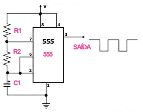
To carry out flow measurement, it is necessary to have a specific electronic circuit to generate the mechanical waves and another to detect the waves received. The first circuit we implemented is the pulse train generator, responsible for generating square waves that alternate between high and low logic levels. These waves operate at a frequency of 40 kHz and with a cyclic ratio of 50%, which are ideal specifications for the operation of ultrasonic transducers. The pulse train generator is obtained using a famous integrated circuit in electronics, the NE 555, which has been configured to operate in astable (oscillator) mode.
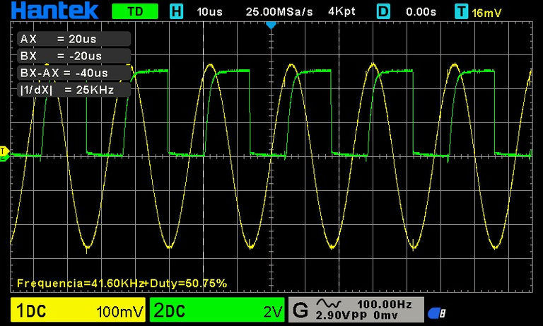
On the other side, the signal received by the ultrasonic receiver (in yellow in the image below) is a sine wave of the same frequency (40KHz) and the same cyclic ratio (50%), which, behind a comparator circuit, is transformed into a square wave. When the air flow passes through the tube it generates a phase difference between the transmitted and received pulse trains, so this phase difference is what allows the flow to be measured, the higher the flow speed the greater the phase difference.
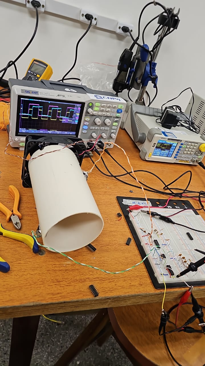
In the picture below, we have the PVC pipe and at each end we have the transceivers: transmitter and receiver. Also used to generate the air flow is a cooler, whose speed is regulated by adjusting its supply voltage. In the protobord we have the circuit assembled and at the bottom of the tube the oscilloscope which shows the pulse train waves of the transmitter (in blue), the receiver waves (in purple) and the phase difference between these waves is given by the wave in yellow.
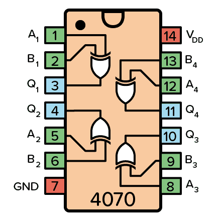
The phase difference (yellow wave) is obtained through an XOR logic gate (exclusive OR). The integrated circuit used is the CD4070, which has a truth table where the output will only be logic level high (1) when the inputs are different and logic level low (0) when the inputs are the same.
We're still in the process of collecting results, but what was asked was to emphasize the problems of measuring air flow. To be honest, the electronics alone have been a lot of work and the flow measurement part will be a bigger problem. Wish us luck in completing this lab!

[PT]
Olá, Comunidade Hive!
Estou cursando mestrado em Engenharia Elétrica e decidi compartilhar minhas aventuras acadêmicas sempre que possível. Recentemente, tive a oportunidade de me matricular na disciplina de Instrumentação Eletrônica. Embora eu goste muito de eletrônica, isso não garante que será fácil ou que eu me sairei bem!
Na primeira semana da disciplina, o professor preparou nosso primeiro laboratório, que consiste em medir o fluxo de ar. Existem vários métodos para medir o fluxo, cada um com suas particularidades. Alguns métodos são mais adequados para medir fluxos a baixas velocidades, enquanto outros são melhores para altas velocidades, entre outras variáveis. Resumindo, medir fluxo é realmente um desafio!
Para nossa medição, utilizaremos transdutores ultrassônicos: um transmissor e um receptor. O experimento envolve a passagem de um fluxo de ar por um tubo, onde um transmissor e um receptor ultrassônico são fixados a um ângulo de 45º. Mas por que 45º? Esses transdutores emitem ondas sonoras (mecânicas) acima de 20 kHz, o que os classifica como ultrassônicos. Se fossem posicionados verticalmente, as ondas mecânicas poderiam sofrer um efeito de arrasto. Para minimizar esse efeito, os transdutores são inclinados, mas ainda alinhados na mesma linha de visão.
Existem diversas aplicações para a medição de fluxo, que são utilizadas em áreas tão variadas como a medicina, a indústria e até mesmo na aviação (onde esse método é empregado para inferir a velocidade do avião).
Para realizar a medição de fluxo, é necessário ter um circuito eletrônico específico para gerar as ondas mecânicas e outro para detectar as ondas recebidas. O primeiro circuito que implementamos é o gerador de trem de pulso, responsável por gerar ondas quadradas que alternam entre níveis lógicos alto e baixo. Essas ondas operam na frequência de 40 kHz e com uma razão cíclica de 50%, que são especificações ideais para o funcionamento dos transdutores ultrassônicos. O gerador de trem de pulso é obtido por meio de um Circuito Integrado famoso na eletrônica, que é o NE 555, que foi configurado para operar no modo Astável (oscilador).
Do outro lado, o sinal recebido pelo receptor ultrassônico (em amarelo na imagem abaixo) é uma onda senoídal de mesma frequência (40KHz) e mesma razão ciclica (50%), que atrás de um circuito comparador é transformada em uma onda quadrada. Quando o fluxo de ar passa pelo tubo ele gera uma diferença de fase, entre o trem de pulso transmito e o recebido, então essa diferença de fase é que permite medir o fluxo, quanto maior a velocidade de fluxo maior será a diferença de fase.
Na figura abaixo, temos o tubo de PVC e em cada extremidade se encontra os transtudores: transmissor e receptor. Também para gerar o fluxo de ar temos um Cooler, onde sua velocidade é regulada ajustando se a sua tensão de alimentação. Na protobord temos o circuito montado e ao fundo do tubo o osciloscópio que mostra as ondas de trem de pulso do trasmissor (em azul), as ondas dos receptor (em roxo) e a diferença de fase entre essas ondas é dada pela onda em amarelo.
A diferença de fase (onda em amarelo) é obtida através de uma porta lógica XOR (OU exclusivo). O circuit integrado utilizado é o CD4070, que possui a tabela verdade onde a saída somente será nível lógico alto (1), quando as entradas forem diferentes e nível lógico baixo (0), quando as entradas forem iguais.
Ainda estamos em fase de coletar resultados, porém o que foi pedido foi enfatizar nos problemas para medir o fluxo de ar. Para ser sincero somente a parte eletrônica já deu bastante trabalho e a parte da medição de fluxo será um problema maior. Nos desejem sorte para finalizar esse laboratório!


Posted Using InLeo Alpha