¿Cómo va todo? Por acá estoy de vuelta con un poco más de contenido, aunque esta vez la programación no es el centro, sino más bien un poco de circuitos y electrónica. Esto porque este semestre estoy cursando una materia bastante interesante, se llama "Laboratorio de Circuitos y Electrónica", en la cual he podido poner en práctica varios conceptos que conocí en materias anteriores.
Ha sido muy interesante ver las cosas en la vida real y no solo imaginando el flujo de energía en el papel. Conseguir los materiales fue un poco complicado pero con el apoyo de un compañero ahorre parte del dinero necesario para comprar las herramientas que hacían falta, pues me las prestó, en concreto las resistencias y el protoboard. El multímetro lo compré con algunos ahorros en Hive que tenía en Binance.
What's up? Here I am back with a little more content, although this time programming is not the focus, but rather a little bit of circuits and electronics. This is because this semester I'm taking a very interesting subject, called "Circuits and Electronics Laboratory", in which I've been able to put into practice several concepts that I learned in previous subjects.
It has been very interesting to see things in real life and not just imagining the flow of energy on paper. Getting the materials was a bit complicated but with the support of a colleague I saved part of the money needed to buy the tools that were needed, because he lent them to me, in particular the resistors and the breadboard. I bought the multimeter with some savings in Hive that I had in Binance.
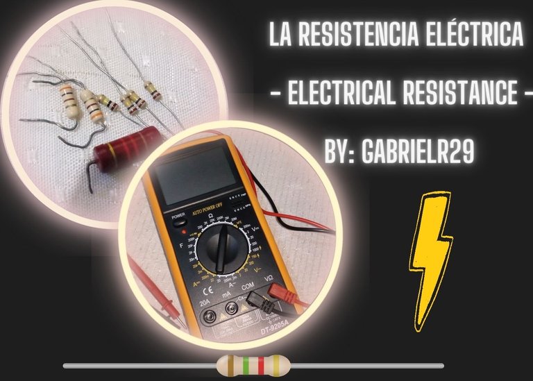
Original Pictures, edition with CANVA

Bien, entrando en materia, es prudente comenzar con la definición... ¿Qué es una resistencia? Pues en el libro "Análisis de Circuitos en Ingeniería" (Hayt-Kemmerly-8va Edición) encontramos que se define como:
El elemento pasivo más simple, considerando el trabajo de Georg S. Ohm, quien en 1827 publicó un folleto que describía sus resultados de las diversas pruebas para medir corrientes, tensiones y describirlos en forma matemática. Uno de esos resultados fue el planteamiento de una relación fundamental llamada ahora "Ley de Ohm", aunque en honor a la verdad, fue descubierta mucho antes, solo que fue un semiermitaño (Henry Cavendish) quien lo hizo, de modo que no hubo tanto revuelo en su momento (46 años antes). Dicha ley establece que la tensión entre los extremos de materiales conductores es directamente proporcional a la corriente que fluye a través del material o: v= R.i
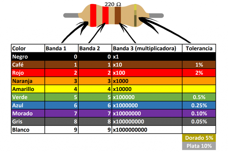
Actualmente, en la electrónica existe un estándar para el cálculo del valor nominal de una resistencia, este se realiza a partir de un código de colores que representa el primer valor, el segundo, el multiplicador y la tolerancia presentes. Un dato a considerar es que es posible encontrar resistencias con más de cuatro bandas, en cuyo caso se añaden cifras según el número de bandas y el multiplicador corresponde a la antepenúltima banda, es decir antes de la banda de tolerancia.
Entonces estos pequeños componentes con bandas de colores los conocemos como resistores o resistencias, aunque el propio término se refiera a la oposición del paso de corriente, por lo que nosotros mismos podemos contar como una especie de resistencia si tocamos demás el circuito durante las prácticas, de modo que corromperíamos las mediciones.
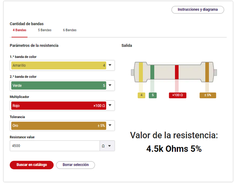
Cabe destacar que existen softwares que facilitan el reconocimiento de los valores nominales de las resistencias, sin embargo, es prudente no depender de ellos, pues "enbrutecen" al estudiante si abusan de sus beneficios. Con esto quiero decir que se acostumbran y luego cuando toca hacer el cálculo a mano, vienen las dificultades.
Well, getting down to business, it is prudent to start with the definition.... What is a resistor? Well, in the book "Analysis of Circuits in Engineering" (Hayt-Kemmerly-8th Edition) we find that it is defined as:
The simplest passive element, considering the work of Georg S. Ohm, who in 1827 published a booklet describing his results of various tests to measure currents, voltages and describe them in mathematical form. One of those results was the statement of a fundamental relationship now called "Ohm's Law", although in all honesty, it was discovered much earlier, only it was a half-hermit (Henry Cavendish) who did it, so there was not so much commotion at the time (46 years earlier). This law states that the voltage between the ends of conductive materials is directly proportional to the current flowing through the material or: V = R.i
Currently, in electronics there is a standard for calculating the nominal value of a resistor, this is done from a color code that represents the first value, the second, the multiplier and the tolerance present. A fact to consider is that it is possible to find resistors with more than four bands, in which case figures are added according to the number of bands and the multiplier corresponds to the antepenultimate band, i.e. before the tolerance band.
So these small components with colored bands we know as resistors or resistors, although the term itself refers to the opposition of the passage of current, so that we ourselves can count as a kind of resistance if we touch the circuit too much during practice, so that we would corrupt the measurements.
It should be noted that there are softwares that facilitate the recognition of the nominal values of the resistors, however, it is wise not to rely on them, because they "enbrute" the student if they abuse their benefits. By this I mean that they get used to them and then when it is time to do the calculation by hand, difficulties arise.
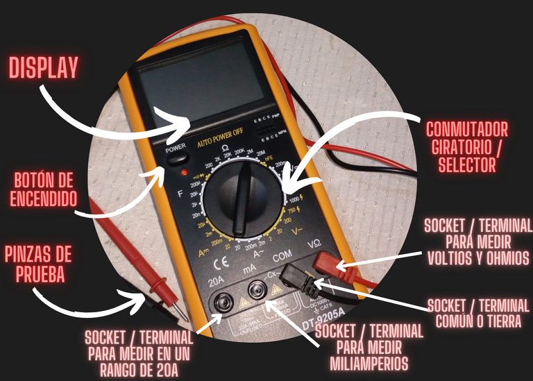
Para conocer mejor esto de las resistencias, la práctica es la clave, así pues ¿Cómo se pueden medir? Pues para ello existe el ohmnímetro, cuya funcionalidad está presente en los multímetros y se encarga de precisamente, permitir la medición de las resistencias a través de dos pinzas de prueba que se colocan a cada extremo de la misma, es decir en sus terminales. El que tengo es uno sencillo que no es de marca oficial pero que me ha ayudado bastante para el proceso de aprendizaje, el modelo es DT-9205A.
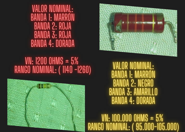
Este tiene un selector, un display (pantalla donde se muestran las mediciones), las pinzas de prueba, los sockets (entradas para las pinzas), y su botón de encendido. Antes de medir es prudente calcular los valores nominales, para esto se emplea la tabla antes mencionada, acá debajo dejo algunas fotos de como me fue con un par de resistencias, aunque por el tiempo que tienen los colores se notan algo desgastados.
Para el rango nominal se resta y se suma el porcentaje del valor resistivo obtenido al mismo para saber en que rango deberían estar las mediciones para determinar que la resistencia está en buenas condiciones o no. Para facilitar el cálculo del valor nominal (resistor de cuatro bandas solamente), dejé una pequeña fórmula acá abajo.
To learn more about resistors, practice is the key, so how can they be measured? Well, for this there is the ohmmeter, whose functionality is present in the multimeters and is responsible for precisely, allow the measurement of the resistors through two test clamps that are placed at each end of it, ie at its terminals. The one that I have is a simple one that is not of official mark but that has helped me enough for the learning process, the model is DT-9205A.
It has a selector, a display (screen where the measurements are shown), the test clamps, the sockets (inputs for the clamps), and its power button. Before measuring it is prudent to calculate the nominal values, for this the table mentioned above is used, here below I leave some photos of how I did with a couple of resistors, although by the time they have the colors are somewhat worn.
For the nominal range subtract and add the percentage of the resistive value obtained to know in what range the measurements should be to determine that the resistor is in good condition or not. To facilitate the calculation of the nominal value (four band resistor only), I left a small formula below.
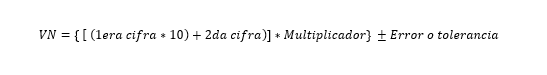
Fórmula para calcular el valor nominal, Word 2013 (Inserción de ecuaciones)
Fotografía original tomada con mi Alcatel 5028A, edición realizada con CANVA
Fotografía original tomada con mi Alcatel 5028A, edición realizada con CANVA
Ahora bien, a la hora de realizar mediciones debemos tener en cuenta algunos detalles como: Tener demasiado contacto de nuestra piel con la resistencia que estamos trabajando puede estropear la medición, también los nervios o la falta de buen pulso genera lecturas extrañas. El desgaste en las resistencias y la falta de iluminación puede llevar a errores en el cálculo del valor nominal, de tal manera que hayan confusiones, por ello es importante tener las resistencias separadas por su valor y así ahorrar tiempo a la hora de armar circuitos.
Hay que considerar que si no se observa cambio en el ohmímetro es posible que haga falta un cambio en el selector, pues el valor de la resistencia se salga del rango establecido, como por ejemplo que el selector esté en el rango de 200ohms pero la resistencia sea de 30k. Un protoboard puede ser de ayuda como soporte para las mediciones iniciales antes del armado final de nuestro circuito. Acá debajo dejo algunos gif de mediciones que realicé para nutrir las explicaciones de este post, estas corresponden a las resistencias antes mostradas.
Como se puede notar, la resistencia más "delgada" marca 96,8 en el rango de 200k, por tanto son 96,8 kilo ohms, entra en el rango nominal calculado. Por su parte la más "robusta" marca 1,17 en el rango de 20k, por tanto son 1,17 kilo ohms, sin embargo aproveché mostrar como el multímetro es más preciso cuando se baja al rango de 2k, pues este es más bajo y más cercano al rango de la resistencia.
Now, when taking measurements we must take into account some details such as: Having too much contact of our skin with the resistor we are working with can spoil the measurement, also nerves or lack of good pulse generates strange readings. The wear in the resistors and the lack of illumination can lead to errors in the calculation of the nominal value, so that there are confusions, so it is important to have the resistors separated by their value and thus save time when assembling circuits.
It is necessary to consider that if no change is observed in the ohmmeter it is possible that a change in the selector is necessary, because the value of the resistance is out of the established range, as for example that the selector is in the range of 200ohms but the resistance is 30k. A breadboard can be helpful as a support for the initial measurements before the final assembly of our circuit. Here below I leave some gif of measurements that I made to nourish the explanations of this post, these correspond to the resistors shown above.
As you can see, the "thinner" resistor marks 96.8 in the range of 200k, so it is 96.8 kilo ohms, it is within the nominal range calculated. On the other hand, the more "robust" one shows 1.17 in the 20k range, so it is 1.17 kilo ohms, however I took the opportunity to show how the multimeter is more accurate when it is lowered to the 2k range, as this is lower and closer to the range of the resistor.
Y bueno, nada más que agregar, esta ha sido mi publicación sobre lo que son las resistencias, inspirado en esta materia tan interesante que he estado cursando este semestre llamada "Laboratorio de Circuitos y Sistemas", desde acá gracias a la profesora que la ha impartido con tanta pasión y a mi compañero que me ha facilitado el protoboard y las resistencias para ayudar en mi proceso de aprendizaje.
And well, nothing more to add, this has been my publication on what resistors are, inspired by this interesting subject that I have been taking this semester called "Circuits and Systems Laboratory", from here thanks to the teacher who has taught it with so much passion and my partner who has provided me with the breadboard and resistors to help in my learning process.